

Introductory views of the A-50
The winter of 2007-8 provided the opportunity to dig into the A-50-1 which had for years lain dormant in the back of "skunk works." Little hope existed for arriving at an airworthy engine like that of the "Cub doctor's" 1938 J-3 which we admired at Oshkosh. More likely it would best serve as a display engine, which was the goal of another A-50 owner we corresponded with. (his had come from Canada, and we learned his name from a posting on the AAA flyin bulletin board, see his letter below).
Secondly, the project allowed for increasing our familiarity with the inner workings of the small Continental, which has such a prominent place in lightplane development and has been the engine which so many pilots remember from their first solo...myself included. There would be some surprises inside this early example to add to the obvious differences from later Continentals. It was what might be called "engine archaeology."
First and foremost among the external differences was the absence of the familiar Continental "kidney tank" containing the oil supply. Instead, an oil inlet and drain port are part of the rear cover and attach to a separate tank mounted on the firewall (Aeronca) or suspended below the motor mount (Piper). This would describe a "dry sump" arrangement properly, though Continental literature continued to call the kidney tank engines "dry sump" types. Certainly the oil was nowhere near the crankshaft in either case. No rationale has been discovered as to why this arrangement disappeared after the first year of production, but leakage issues might be suspected. (another thought: eliminating miscues by the airframe manufacturer who would have to install this critical system) For our engine, at least, no evidence emerged indicating oil starvation throughout its life. In Johnny Jones' transcontinental flight, this design allowed for a simple increase in oil supply by merely installing a larger oil tank.
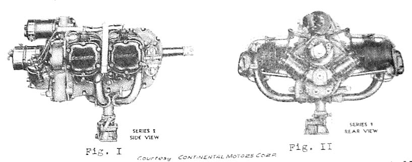
Next, the "top exhaust" cylinders. These mark the earliest "A" series Continentals into 1939, first with cast exhaust manifolds which were subject to cracking and rapidly disappeared in favor of welded tubing. Our engine would probably have been delivered with the cast manifolds, which we have never seen except in pictures. Unlike the dry sump, the top exhaust cylinders equipped 65 and even 75 hp versions. We missed the opportunity to buy a top exhaust A-75 from Giff Gillingham when he sold us the Pietenpol project (for another $250...that was 1969). Other differences not so readily apparent: the spark plugs are vertical and somewhat shrouded from the combustion chamber. In our case, there is only one plug per cylinder, but the boss for a second plug opposite is obvious. There were 65s with single ignition, but not with dry sumps. 75 and 80 hp models had dual mags and kidney tanks (the first 80's probably were top exhaust). In these fluid early days, the case must have been redesigned first, then the cylinders. The intake elbows are circular in cross section rather than rectangular. Some early drawings (like the ones above) show no elbow at all, but the intake tubing extending right up to the elbow flange. These same drawings show a deeper carb spider with packing gland attachment for the intake tubes in place of the familiar simple rubber hose connections, and four attachment points on the case (see above pictures). Haven't seen one of those either.
Another difference is the pushrod tube arrangement. Instead of the tubes being fixed into the cylinder head, they are fixed into the cover which bolts to the case. These covers are cast iron. Rubber tubes with clamps attach at the head. We found a picture of an up exhaust 65 which shows this same feature.
A different pushrod tube arrangement
For all these differences, the moving parts required few changes. Our interchange manual indicates the same part number for the crankshaft on our engine goes all the way up through the C-85!
Before proceeding further, I want to insert a wonderful dissertation on the A-50 by Chris Bobka, who owns an Aeronca 50C, writing on the Taylorcraft Foundation discussion forum:
(from T-craft forum archives - by Chris Bobka)
Doug,
You really know how to ask simple questions! Sorry to be tardy in getting back to you but here is the first installment of the lineup as I see it: The A-40 is not part of the A series as it is a different design altogether and discussion of it will not be had here. See Chet Peek's new book "Flying with Forty Horses".
All (the other) A series are 171 cu in displacement 4-cylinder with 3-7/8" bores and 3-5/8" stroke. The number after the dash is the rated horsepower: either 50, 65, 75, or 80. There is an obscure hybrid variant of the A series called the A-100 and that will be discussed at the end of the series. It is a favorite of mine.
First, the A-50 series:
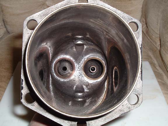
The A-50 series dash numbers range from the -1 consecutively to the -9. Some A series have up exhaust, meaning the intake port is on the bottom of the cylinder and the exhaust port is on the top of the cylinder. Up exhaust engines include the A-50-1, -2, -3, -4, -5, and -6. The A-50-7, -8, and -9 utilize a cylinder with a down exhaust. Some of the cylinders have only one spark plug hole, on top, with a cast boss where one could concievably add the lower hole. These are used on the A-50-1, -4, and -7 and, obviously, these engines only have one centrally mounted magneto driven directly by splines machined into the rear of the crankshaft. This makes this crankshaft very unique to the original A-50 series. This crankshaft equips my very orignal A-50-5 that utilizes dual mags, even though the splines are not used to drive anything.
A single ignition cylinder from the A-50-1
The A-50-2, -3, -5, -6, -8, -9 series all have two spark plugs per cylinder and use dual magnetos. The dual magnetos are driven off of a gear bolted to the back of the crankshaft so these mags turn the other way from the single mag setup. So some up exhaust cylinders have one plug and other up exhaust cylinders use two. Same for the down exhaust cylinders. Single ignition models were not allowed to be certified after 11/7/41.
The intake elbows used on up exhaust engines have a round cross section going to a round cross section. The intake elbows used on down exhaust engines have a square cross section going to a round cross section.
Magnetos are generally the SF-4L or AM-4 (with left hand rotation) for the single mag and SF-4R or AM-4 (with right hand rotation) for the dual mag models. However, the A-50-2 is certified only with Dual Bendix Scintilla WL-4 mags or an Autolite IGW battery ignition (like the point system on your 1959 El Camino). In addition to the SF-4R and AM-4, the A-50-8 and -9 can also use dual Case 4-CAMA mags. Magneto timing varies from model to model anywhere from 24 to 28 degress BTDC with some timing different between left and right mags. Impulse equipped magnetos and what they fit will be discussed later.
Rare views of the "dash 2" with distributers; battery ignition
ever see one?
The A-50 series engines utilize a 5.4:1 "low" compression ratio and utilize a different piston from the other horsepower engines because of this. Holding them in my hands, it appears to be the same casting as certain A-65 pistons except that the flat top is machined a little lower.
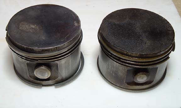
Pistons "before and after" cleanup
The low compression A-50 series makes its rated power at a low 1900 RPM but yet usually uses a really large prop. The prop for my Aeronca 50-C is a 76-51. Big diameter and high pitch. What? On a 50 hp engine? Compare this to a 72-42 used on an A-65. Big diameter equals really big disc. Think how a 50 hp helicopter can lift up vertically with a big prop turning really slowly... Don't laugh at a 50 hp continental...One famous modestly modified Aeronca 50-C flown by Johnny Jones flew from Burbank to NYC over Thanksgiving weekend in 1938 NONSTOP and landed with enough fuel to go 700 more miles!! I would like to recreate this flight one day!!
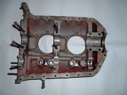
Some of the A-50 engines utilize a "dry" sump crankcase/accessory case combo utilizing a remote oil tank. These are the A-50-1, -2, -3. The accessory cases I have for these are both of magnesium and I do not know if any where ever available in aluminum.
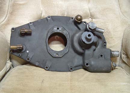
This is the case cover described above
The A-50-4, -5, -6, -7, -8, and -9 crankcase/accessory case combo all utilize a 4-1/2 qt. kidney "wet" sump. Obviously, a "dry" sump crankcase cannot be used with a "wet" sump accessory case and vise versa.
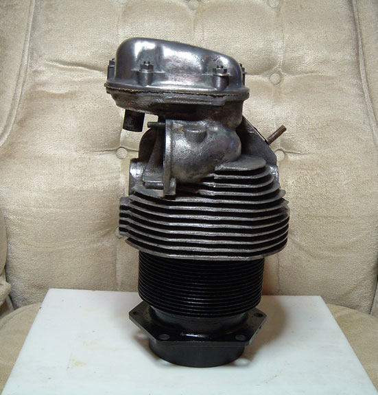
(question for reader: which engine is shown at the beginning of the page?
...it must be a "dash three", right?)
A-50 series cases made prior to serial number 115395 (around late 1939) use a "hard mount" meaning that, if I remember right, four 5/16" bolts hold the engine to the motor mount without any rubber vibration damping. It was expected that the airframe designers would make motor mounts that would incorporate rubber suspension. This was rarely the case, however, and subsequent serial numbers incorporated the conical rubber mount bosses that we see most prevalent today.
A-50 series engines generally are equipped with Bendix-Stromberg NA-S3, NA-S3A1 (the A1 meaning mixture control equipped), or Marvel-Schebler MA-3-PA carburetors. 1-1/4" venturis on the former and 1-7/32" on the latter. However, the A-50-4J, -5J, -6J, -7J, -8J, -9J models use a High Fuel Injector Model A in place of the carb, hence the J suffix. All other aspects of these engines remain the same.
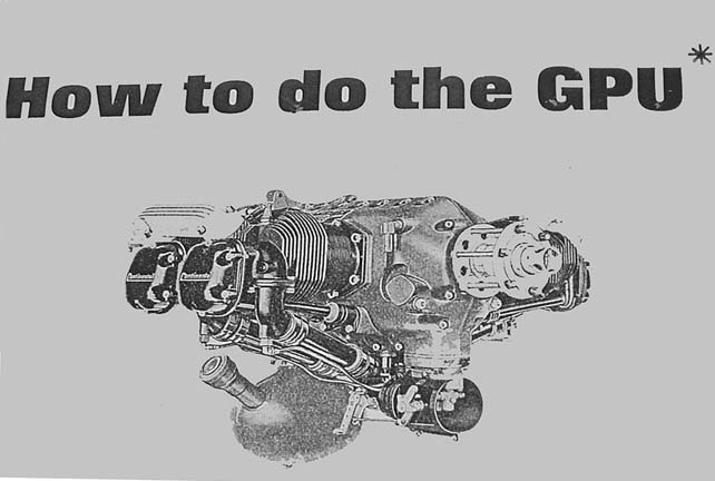
* GPU is ground power unit; this is a teaser for another project
involving the PC60 Continental. But, which model is this one?
It looks like single ignition; that's a "dash 4J right? Note the cast
exhaust manifolds. Ever see one?
The unique crankcase, accessory case, and gear train on the A-50-6, -6J, -9, -9J allow the use of either an Eclipse Type 625 or E-80 electric starter or a Mechanical Hummer X starter. The accessory case has the magnetos mounted horizontally, one left and one right with the "tops" of the mags pointing at 3 and 9 o'clock. Non-starter dual mag equipped accessory cases mount the mags almost vertical, one left and one right with the "tops" of the mags pointing at 11:30 and 12:30 o'clock. Conversion is difficult, if not impossible, because the 20 or so parts you need are scarce. If you want these features, you really have find an engine already with them. (my confession; got one of those too)
Some of the crankcases are cast and machined to accept an AC diaphragm fuel pump just like the one on your 1959 Chevy El Camino. It runs off an eccentric bolted to the front of the camshaft. I am unsure if a fuel injected engine can be equipped with a fuel pump, though, because the fuel injector pump runs off of a gear that mounts to the same part of the camshaft. The fuel pump equipped models were intended for use in low wing aircraft that had wing tanks, like the Ercoupe.
All A-50 series crankshafts had an SAE No. 0 tapered output shaft and utilized a separate hub and key for attachment of the propeller. I have an original early A-50-5 and it is very apparent that the innards are of lighter wieght than later versions of the A series. The crankshaft has well drilled crankpins. The gears have lightening holes drilled in them.
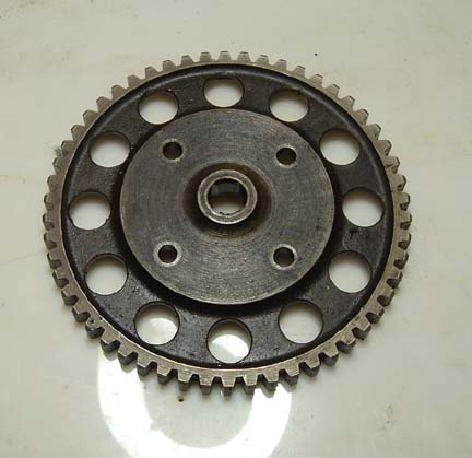
Sure enough, the parts book shows a solid gear
the holes would have been cast in
The connecting rods are a slimmer design. Nothing wrong with all this. Just an observation. I would not be using these lighter components to build up a 65 or higher HP engine, though. So you have to know what you have.
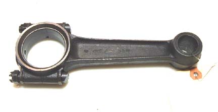
The Atlas #5315 rod; note the nuts on the cap side
"Dry" weights range from 160 to 176 lbs. There are other comments to be made about the A-50 series but they will wait until discussion of each of the A series engines is complete. The A-65 is for next week.
(alas, we are still waiting, but here are some feedback comments;)
Chris,
What a wonderful dissertation on the A-50. I can hardly wait to read your entire series. Are you thinking of writing a book? I have a set of single ignition, upstack cylinders, complete with rockers, valves, pistons. All in really nice condition. I can't recall what they measured at, but can do it again. Do you know anybody out there who might be interested in them? A camshaft also came in the deal, and I have wondered if it is the same as an A-65.
Dick Fischer
Mr. Bobka:
Thanks for your piece on the A-50 in the Taylorcraft forum archives! Very informative. This winter I am taking apart my A-50-1. Here is a question for you: my rods are embossed #5315 Atlas, 2 and a horizontal "G"; they have the nuts on the bottom side! The parts book shows A-50 rods with the nuts on top. The shank is shaped to accept the flat-sided bolt head and the caps accept the nuts. Ever see these?
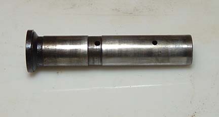
Second: the rear of my crank is threaded, the single-mag drive plate appears to be splined into the gear; removing the bolts backed this assembly away in one piece.
Finally, I agree with your thoughts on prop size. It would be interesting to compare the THRUST of the 50 with its larger disc area to that of the 65. I'm guessing it would not be as great a percentage of difference as the percentage of rated horsepower difference. I attach some correspondence with another A-50 owner, Jim Zazas. I still have never seen an Aeronca firewall oil tank.
-Bob Greenwall
* * *
One general observation: the whole subject of "pickling" engines, using dissicant plugs etc. may have merit regarding freshly overhauled engines, but judging from the internal condition of this engine, one that has been run for a few hundred hours is so well coated with oil and deposits inside that it is perfectly preserved. Not a sign of corrosion with the exception of one small spot on a through bolt up near the case nose. No exceptional measures were employed in storage beyond keeping the case in plastic and the jugs in plastic buckets.
Now some general observations about FAA regulations. A recent session at the local airport liars' club revealed that engines do not have annual inspection sign-offs. They are checked for condition pertinent to the airframe in which they are installed. "Installed" is a key word, for should that in any way change, it would require the signature of a certified mechanic with inspection authorization who would determine that any replacement engine was on the equipment list for that airframe type. The inspection authorization is not required for doing engine work, just the A & E rating. (actually just the "E" rating)
What about an old engine not on an airplane?
If that engine passed a condition inspection, was of proper type, had its original data plate, and had either original logs or replacement logs with estimate of hours on it, would it not comply with regulations? If an IA entered the installation and passed the annual? Certainly that log book could only show work done on the engine signed off by a rated mechanic. And it is also true that before any authorized person did so, they would want to know what was in that engine from the ground up with their own eyes. That would only be reasonable.
So, for the sake of discussion, any disassembly, measurement, reassembly described here should only be taken as generic; done to no particular one engine but one of several we have lying about through the many years we have had them and memory grows dim as to which one, etc.
* * *
(first-time case splitters)
While these experiences are fresh in mind, I want to share them with other "first-timers". This applies to an A-50-1 but may well apply to all small Continentals. First it is assumed that one reads and comprehends all of the overhaul manual and the excellent online posts. I found yet more to the story. (there are some great tips on bowersflybaby.com, "Harry's engine page") When removing the nuts from the through bolts and the small bolts around the parting line of the case halves, the following unexpected situation appeared. Most of the bolts come out easily, but there are two which were oversized...I suspect they are for indexing or precision alignment of the case halves since one is at the upper rear and the other at the lower front. Thus, they will be the first installed when reassembling. Naturally, the front one was the one of two I left in while repositioning the case to horizontal. It was in there tight, was one of the long ones, and required a special C-clamp rigged as a tool to press it out. Lesson #1
First-timers such as I may be surprised that some of the cylinder studs are also through bolts and disappear into the case as it begins to spread apart; these are at the front and rear only. So, if you have run a nut onto one of these you are not going to separate the cases. You may guess how this was discovered. Lesson #2
The case halves seemed stubborn at the rear. The crank was rotated to check that there was no binding. But the cam would not rotate. In order not to lose the cam gear capscrews, you may be tempted to run them back in the cam flange for safe keeping. You may run them in far enough to encounter friction so they will not work out when handled. If you do so, they will hit the case and bind so that the cases will not separate. When you back them out, if everything else is right, your case will separate nicely as mine then did. Lesson #3
The rosey glow we are attributing to Marvel Mystery Oil
The insides looked amazingly good. The rear case cover felt very light, was darker gray than the case halves, and made one think of magnesium. Indeed according to Chris Bobka they were indeed magnesium. Only one mag, driven from the rear of the crank. Two breather tube outlets at the top rear...one for overboard and one to equalize the remote oil tank (it took a while to figure that one out). All the crank and rod bearings were .010 under, and so marked. All the clearances were within service tolerances. The shaft runouts were as well. Now we began to think about it possibly being airworthy after all. Ever since the Iowa Western A & P school overhauled our A-65 and sent it back in shiny aluminum finish, we favor that look over paint on an engine...orginality aside. So the long winter has been whiled away cleaning those aluminum parts of all paint as well as oil and dirt. No chips or wear marks on the gears. Bobka mentions the gears have lightening holes by contrast with 65s. The cam had very little discoloration on the lobes and runout was in limits. Two of the lifter bodies were belled out at the pushrod ends enough to prevent their being withdrawn from the case without some stoning down. Colvin's Aircraft Handbook recommends a "Pike stone" to remedy all kinds of possible gross blemishes. The pushrod cups had flaking away of the rims on a couple examples. The lifters in the parts drawings look different than ours.
Our postwar parts book shows something different
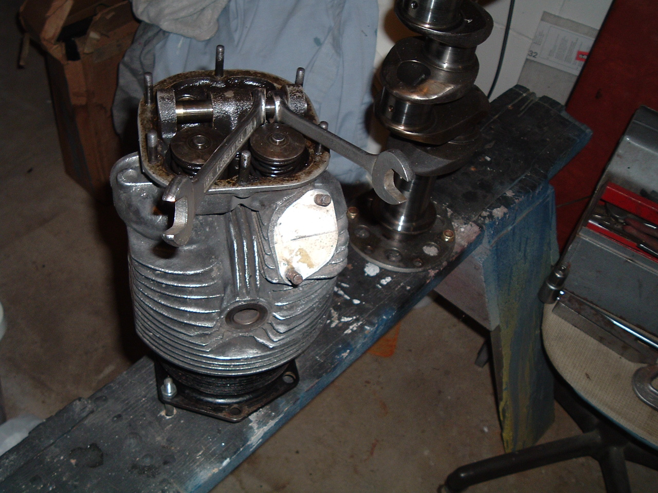
On to the cylinders. One jovial type opined that all the special tools one needed to overhaul a Continental cylinder was a fence post and a claw hammer. What impudence! It is true that removing the valves does involve restraining them with a section of 2 x 4 while depressing the husky retainer with "suitable tools" which some have taken to mean two screwdrivers. My picture shows a more advanced method. (I did acquire a real valve spring tool from surplus once, but it did not fit...it did give a good idea of what was required however). The cylinder bores were clean, smooth and corrosion free.
Pretty encouraging after 70 years
There was some alarm to find three different numbers on the exhaust valves. All proved to be Continental numbers, however. The intakes all matched but did not appear in Continental books...apparently too old though clearly Continental numbers. The earlier valves had two-groove retainers and the later single-groove. All of the valves had clean seating surfaces, but were out of limits in the guides. I asked my supervising mechanic how difficult guide replacement might be. His response was typically memorable. After procuring a mandrel which enters the guide from the bottom, extending beyond the cylinder base, you simply "smite it." (possibly with the claw hammer mentioned above)
Here's that fixture; the crankpin holes are 1-15/32 inches +- by the way
* * *
The subject of valve guides leads into the subject of economics. The price of valve guides has gone from $2.75 to $17.50 since my last order. Granted thirty years have ensued. There was a real windfall when the Army Air Force released surplus Continental parts. They stockpiled literally "stock piles" of parts when purchasing planes like the L-2, L-3 and L-4. For years, these parts were available at reasonable prices. They still are, except what now does the word "reasonable" mean? Also, these good old vendors are getting old and cranky like the rest of us. This reminds me of the story of the parent who gasped when Johnny came home with "a $100 dog". "It's all right, I traded two $50 cats for it." To update this story, if that were possible, the numbers would have to be inflated. There are a lot of $50 cats in the airplane world. For example, were I to get one-half list price (used) for my crank, it would be about three times what I paid for the whole engine, and I paid top dollar!
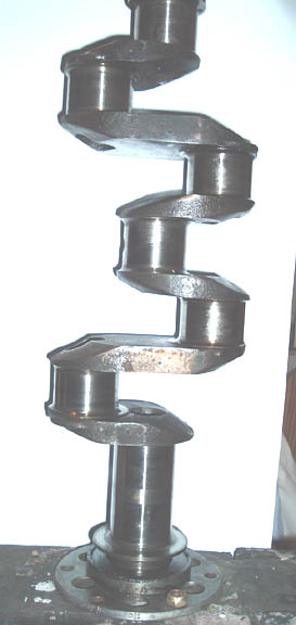
A strong heart, on my sawhorse fixture
* * *
To the topic of pistons. On my last annual, the gurus were listening to my 65 while rotating the prop back and forth, and heard a piston skirt slap against the cylinder walls. These guys were good, one could smell Marvel Mystery oil on the spark plugs! These were 3-ring pistons and you should not hear a similar sound on my 50 because there is an additional ring at the skirt base. Beside these variants, there is also a 5-ring piston. Evidently Continental tried it every way. 50's have 5.4-1 compression pistons. 65's and 75's have 6.5-1 compression, and 80's go 7.55-1. 50's should tolerate any octane rating out there, and not overheat either. It would be very tempting to put in 65 pistons which would go right in (the smaller of two wrist pin diameters would be required). My rings looked very good, the fit in the lands was all within limits...but the end gaps were out. The last ring set was $7.75; now $67.50. My pistons match and look good. There is one chip out of a bottom land which will benefit from the "pike stone" treatment.
* * *
correspondence:
Archaeology report on the A-50:
There were apparently two overhauls done on it. The crank is .010 under, as determined by the bearing markings, and the journals are real nice with the radius preserved into the throws. Mineral solvent did not have much effect on the red residue in the case, but detergent and water did. Could it be from Marvel Mystery Oil? My interchange manual shows that this crank goes all the way up to the C-85. The picture of the case shows one lifter body still in...that is because the pushrod end was belled out. It had to be stoned down a bit to get it out. There is a removeable pushrod cup, and two of them had flaking around the lip. We'll have to look closely at the pushrods.
Suggestion of a second, less professional overhaul are unfortunately found in the presence of an "odd rod". One cylinder had a rod with a C-85 number and quite out of conformity with the others. Another unusual thing: the other three rods have the nuts on the cap end. All replacement rods are shown in the overhaul manual as having the nuts on the shaft end, which makes them easier to access when a cylinder is removed as in a top overhaul. I will have to check online to see if anyone else has encountered such an "early" rod. Also we'll be weighing these; the 85 rod looks beefier.
Talked with a gent who advertized for A-50-1 parts: he had not done hands-on work but said he got his in Canada and was doing a museum display plane. I was in hopes he knew something about the firewall oil tank, but no luck. Pipers used a cylindrical tank suspended beneath the motor mount behind the carb.
Connecting rods: my A50 originals are labelled "Atlas" and number 5315. I read that A40's used off-the-shelf automotive units...don't know about A50s. The latest parts books show 3515 8 and 3515 9(drilled cap) for rods. Do you suppose they reversed the first two numbers to indicate the bolts oriented the opposite ways? That would make 5315.. (mine are oriented nuts on the cap side, late part books show them the other way) In an old Franklin drawing the rods are labelled 5380...sounds like an Atlas number too. Big ends are 2 inch, pin end is 1 inch, length on center looks like 7 3/8 inches. Pretty standard, but 1938 automotive parts aren't that accessible either, are they? The Franklin nuts are on the cap side too. This old 1942 book is very candid about parts sources; Perfect Circle and Simplex rings, Lo-Ex pistons, Alcoa crankcase etc., that candor seemed to go away in later sources.
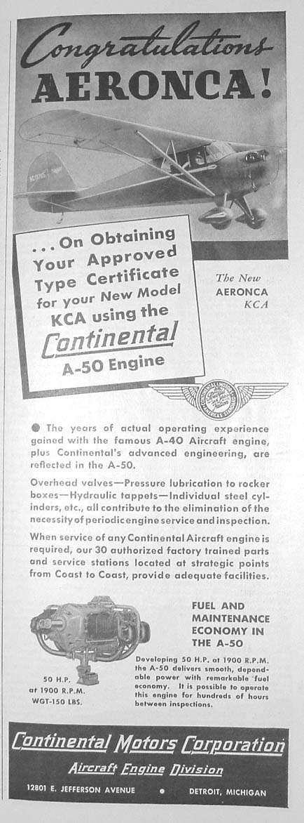
Continental's July '38 ad congratulating Aeronca
The pictures show how different, especially the rear case cover, is from the later Conts. The inlet & outlet for the dry sump oil tank, the oil screen/temp bulb facing down, the single mag mount and...what are those upper fittings? Must be crankcase breathers since there is none up at the ususal front right location. Dual breathers! Also the pressure relief spring (under the brass acorn) goes in from the side on later rear covers, which were more dished out. The distressed look of the tach drive housing is due to its having reverse threads!! The manual is very clear, but I intend to paint an arrow right on it. These engines listed at #150 lbs, no more than the A-40.
Since the data plate was so obliterated I wasn't optimistic about its certifiability...but the essentials were stamped in and comparing it with a repro plate to see what went where revealed the original serial # was there (32181), as was the following: rated H.P. -50, compression- 5.4, venturi- 1 1/4, ATC#-19, max rpm-1900, cruise-1800, min fuel octane-65. The KCA's original engine # was in the 11xxx range so this one must be somewhat later. The dash-1s were only made in '38 though I think. A fellow in Minnesota makes great replacement data plates, but now the FAA forbids their use. Could I legally place one beside the original one "for reference only"? Or better yet, right over the top? Please do not forward my question to FAA.
(letter to Mr. Zaza)
I have an Aeronca KCA which originally carried A-50-1, serial #11581. In its first year it received a dual ignition upgrade. It later had engine #15883. When I got it it had an A-50-9 engine, #144449.
Later I bought an A-50-1 without logs... It was the first one I had ever seen and to date have seen two more. One is on the J-3 which I believe is owned by Clyde Smith. Mine still has its data plate and is serial #32181. I can't recall anyone deciphering Continental numbers, but the second-to-last digit of "8" is common to these -1 engines; and the year of production would have been 1938. (note: the last number is the same as the "dash" number of the engine on these examples ??) (note #2: are the numbers before this the production sequence? If so, mine is the 321st made)
There are a couple of peculiar things about this engine and you may know the answers:
-have you ever seen an Aeronca firewall oil tank? The only clue I have is from the pictures of Johnny Jones trans-continent plane. It appears to be wedge-shaped. The tank that came with mine is shaped like the cylindrical tank on the J-3, but bigger and home made. I have never read or heard why the separate tank arrangement was abandoned...but could guess. For a time I was puzzled why there were two oil breather fittings on the case. Actually they are on the top of the rear case cover (are yours?) Then looking at a generic schematic for dry sump systems it showed an equalizing vent line from case to tank; that must be it. Mine has a baffle beneath these breather ports on the inside attached by rivets through the outside of the cover. The KCA firewall has the attach fittings for the tank.
-The mag drive slotted plate is inserted into the rear of the crankshaft. How do you get it out? The Eismann LA-4 on mine had a fabricated spacer of steel setting it out an inch or so from the accessory case. It has an impulse; I'm thinking that might be the reason.
Hi, Bob:
No problem. I enjoy sharing what information I know. From all indications, it seems you have a very early Continental A-50-1, somewhat earlier manufacture than my A-50-1.
My Continental A-50-1 is serial number 63481. (note the "8" again -Bob) According to Continental Teledyne records (I wrote to Continental to request the information), this engine was built on December 9, 1938 and shipped to Piper Aircraft on December 13, 1938.
What better way to spend a winter?
Just a visual inspection on mine as I removed the jugs shows two immediate problems: a piece of ring land is broken out on one of the 4-ring pistons and a rod has discernable play on one of the crank throws. Guess I'll take a deep breath and remove that rod one of these days. (that rod bearing was fine, and the side clearance ok also) On the positive side, the Continental Interchangeable Parts Manual I downloaded yesterday says all "A" series taper shafts interchange. Thanks for your time, Jim.
one of these had the manual:
According to records provided by Clyde Smith, this engine was installed on a Piper J-3C-50 Cub Trainer in April 1939. This airplane was registered as NC22930, serial number 2837, and was built on April 3, 1939 with a rollout date of April 6, 1938.
Moreover, Clyde said the oil tank installation that went with this engine was identical to an installation he did in 1995. The oil tank was cylindrical and was mounted horizontally under the back of the engine. The oil lines were rubber with brass fittings. According to Clyde, no drawings are available.
I found one of these oil tanks at the EAA Fly Market two years ago and plan to have Clyde restore it with the engine. I plan to overhaul the engine, then pickle it for long-term public display.
I have no logbooks for my A-50-1 engine, which I found in Canada and had shipped here. My other A-50 is a dual ignition A-50-5, which I bought here in the USA. I am still researching this engine.
I cannot provide any specific answers to your questions. I suggest you contact Clyde Smith for answers about the oil tank. He may be able to shed some further light. Likewise, check with Steve Krog of the Cub Club. He may not have the answers you seek, but he will most likely know somebody who does. Also, give Don Swords at Don’s Dream Machines near Atlanta for answers regarding the interchangeability of “A” series engine parts. I believe you can do so without any problem, but Don will be able to provide a more definitive answer.
Sorry I could not have been more helpful. These old engines are great fun, but it takes lots of digging to find answers. I’ll keep looking on my end and will holler if I uncover any further information.
Good luck in you quest! Please feel free to write if you have any other questions.
Cheers and Happy Holidays!
Jim Zazas